Mesh Engine.
Documentation
A Unity editor tool for partitioning large static models, generating LODs and repeating the workflow across batches.
On this page
Overview.
Mesh Engine prepares static models in the Unity Editor by partitioning their geometry and generating levels of detail (LODs).
Open Tools > Infinitus Interactive > Mesh Engine, choose a source, review the settings, then select Generate to create partitions and LODs. The result provides Show in Project and Select generated object actions so you can inspect and repeat the run. Start with the Quick Start.
Profiles and batch processing are available when you need them. Neither is required for a first result.
Guides
| Guide | Use it for |
|---|---|
| Installation and Setup | Importing the tool and preparing a source |
| Quick Start | Generating, finding and repeating a result |
| User Guide | Settings, profiles, batch runs and output management |
| Compatibility and Limitations | Input requirements and processing boundaries |
| Troubleshooting | Resolving a blocked run or unexpected result |
| Support | Contact details and useful evidence |
| First Release | Included features and project requirements |
| Third Party Notices | Included code notices and model license |
Demo scenes
The Plant examples are under Assets/InfinitusInteractive/MeshEngine/Demo/Scenes:
01_QuickStart— partition the150-P-103pipe assembly and compare its generated LODs.02_BatchWorkflow— process three components with shared settings and one source's LOD/output overrides.03_PlantShowcase— compare the prepared Complete plant source across its two reduced LODs.
Start with 150-P-103 for a smaller generation task. The complete Plant example demonstrates scale; regenerating the full model takes substantially longer.
Each demo opens its Scene-view guide on Get started, with instructions, Select source and Open Mesh Engine. Switch to Compare to inspect the supplied source and LODs, use saved viewpoints or frame the subject. New generation creates independent results; inspect those in the Hierarchy and disable them before returning to the supplied comparison.
Before reproducing a demo, keep only its intended sources in the Models queue. Loading a profile retains the queue and per-source overrides; confirm each row uses Shared settings before applying the Batch example's documented overrides.
Mesh Engine preserves whole triangles when partitioning. Reduced LOD percentages are targets, and protection of existing boundaries can retain more geometry. Review the achieved counts and visible result before using an output in your project.
Installation and Setup.
Import Mesh Engine into a Unity project matching the tested versions in Compatibility and Limitations, and let Unity finish importing assets and compiling scripts. The tool and documentation belong under Assets/InfinitusInteractive/MeshEngine; keep that folder structure so the editor can find its interface resources.
Open Tools > Infinitus Interactive > Mesh Engine. The window can be docked beside the Scene view. You can proceed directly to the Quick Start without creating a profile.
Project setup
The supplied demo materials use Universal Render Pipeline (URP). Use a URP project to inspect those scenes as authored. Mesh Engine does not require Unity's Input System package or a change to the project's input backend.
Keep your project's shaders and source materials available. Mesh Engine copies material assignments; it does not convert materials between render pipelines. See Compatibility and Limitations for the source requirements.
For optional higher-quality demo lighting, try a shadow distance of about 200 world units, a 4096 main-light shadow map, four cascades and soft shadows in your active URP asset. The distant full Plant overview needs that wider shadow coverage. These settings increase rendering cost; adjust them to your project and performance budget. Appearance also depends on your other rendering settings. Mesh Engine does not switch or override your project's render pipeline automatically. In Scene view, use Shaded with Scene Lighting and Effects / Post Processing enabled to see the authored lights and grading. The demo camera also shows them in Game view before Play.
Prepare a source
Choose a static scene object, prefab, FBX model asset or Mesh asset. For an imported model, enable Read/Write in its model importer and apply the change. A selected hierarchy can contain several mesh renderers; Mesh Engine analyses the included static geometry together.
For a first example, open Demo/Scenes/01_QuickStart and use Select source to select 150-P-103. Alternatively, instantiate Demo/Prefabs/Plant_150-P-103_Source.prefab while retaining its saved root transform. Follow the Quick Start for the supplied profile and Shared-settings check. Save a working scene if you want its source references available after restarting Unity.
For the full Plant example, use Select source in 03_PlantShowcase, or instantiate Demo/Prefabs/Plant_Complete_Source.prefab while retaining its saved root transform and material assignments. This prepared source includes the vessel material grouping used by the supplied result.
Choose a destination inside Assets, or leave Output folder (shared) empty to use the default Mesh Engine Generated folder. Keep Output policy set to Keep existing for independent results. The window shows the destination before generation.
Reuse a setup
Once you have useful settings, open Configure > Advanced settings > Settings profile (optional) and choose Save As…. To apply an existing profile, assign it and press Load. Assignment alone does not change the working settings. Profiles store shared settings; they do not store a source queue or its overrides.
Quick Start.
Choose a source, review the settings, generate, then find and inspect the result. Open Tools > Infinitus Interactive > Mesh Engine in the Unity Editor.
The wide window keeps a model sidebar visible. In a narrow dock, use Change to open Models. Every queued model is included in generation.
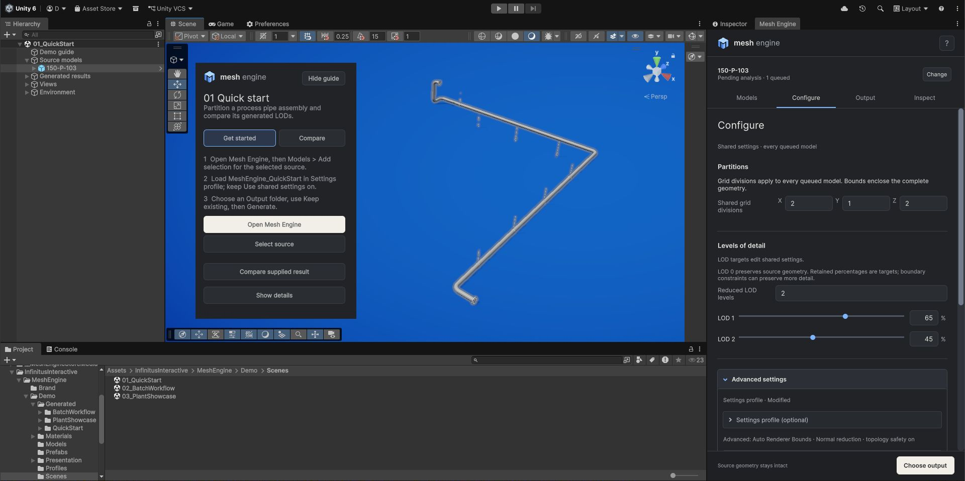
Generate your first result
- Open
Demo/Scenes/01_QuickStart. In the Scene-view guide's Get started tab, choose Select source, then Open Mesh Engine. - In Models, choose Add selection to add
150-P-103. Remove unrelated or duplicate rows so this is the only queued source. Keep its supplied transform. Alternatively, instantiateDemo/Prefabs/Plant_150-P-103_Source.prefab, retain its saved root transform, and add that scene instance. Select Review settings to open Configure. - In Configure > Advanced settings > Settings profile (optional), assign
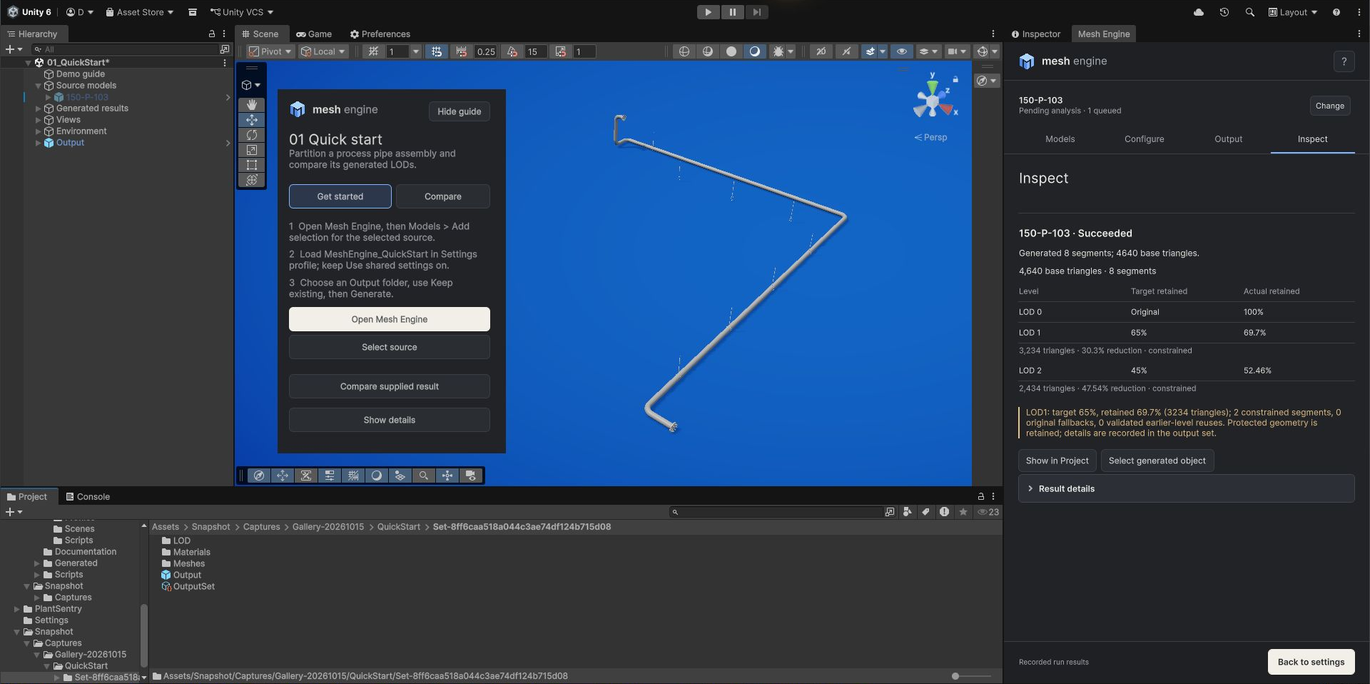
Demo/Profiles/MeshEngine_QuickStart.assetand press Load to restore the supplied setup. Confirm the source row shows Shared; if it shows Custom, enable Use shared settings under Selected source overrides. Review Shared grid divisions of2 × 1 × 2, Reduced LOD levels of2, and retained targets of65for LOD 1 and45for LOD 2. Keep Normal reduction and Topology safety enabled. Select Choose output to open Output. - In Output, keep Output policy at Keep existing. Choose an Output folder (shared) inside
Assets, or use the default. In Output options, keep Create scene hierarchy and Create prefab enabled, with Hide source after success off. This creates a separate set and preserves the supplied result. - Select Generate to create partitions and LODs. If the action is unavailable, follow the message above it; expand Details for the full explanation.
- In Inspect, use Show in Project to find the saved set and Select generated object to select its scene root. Inspect its silhouette, materials and LODs. Expand Result details for exclusions and any constrained or fallback results.
In Configure, expand Partition preview. Preview partitions is optional. Use it before generation when you want to inspect included geometry, occupied regions or exclusions. Preview writes no output assets. After changing the source or settings, refresh the preview.
The supplied 150-P-103 assembly has 47 source mesh renderers. Its generated result contains 8 segments across three occupied cells, with 4,640 triangles at LOD0, 3,234 at LOD1 and 2,434 at LOD2. LOD1 reduces the triangle count by approximately 30.3% and LOD2 by 47.5%. Boundary constraints retain more than the requested targets in two segments at each reduced level; these results use no fallback geometry. Use this example to inspect spatial partitioning, combined geometry and the actual LOD changes together.
Repeat and compare
Change a setting and generate again with Keep existing. Mesh Engine saves a new set, preserving earlier results. Changing the inputs marks the previous result as Previous result; it does not update those saved assets.
Source hiding is off by default. Disable the source or other generated copies temporarily when inspecting one result so overlapping geometry does not obscure it. Re-enable a source you disabled manually before generating again. Save the scene when you want to retain the generated hierarchy.
To replace a result deliberately, choose Replace selected output and assign that set's OutputSet.asset to Exact output to replace. A matching name or folder does not establish ownership. See the User Guide before replacing an output you have edited.
Use the demo comparison
Open Demo/Scenes/01_QuickStart. The Scene-view guide opens on Get started, which provides instructions and the Select source and Open Mesh Engine actions. Switch to Compare for Source, Automatic and individual LOD controls. Use Viewpoint for saved views or Frame model to fit the subject in Scene view.
Compare Source and each LOD from the same viewpoint, checking the silhouette, materials and pipe details. Use Automatic while orbiting or zooming to inspect neighbouring segments as Unity selects their LODs independently.
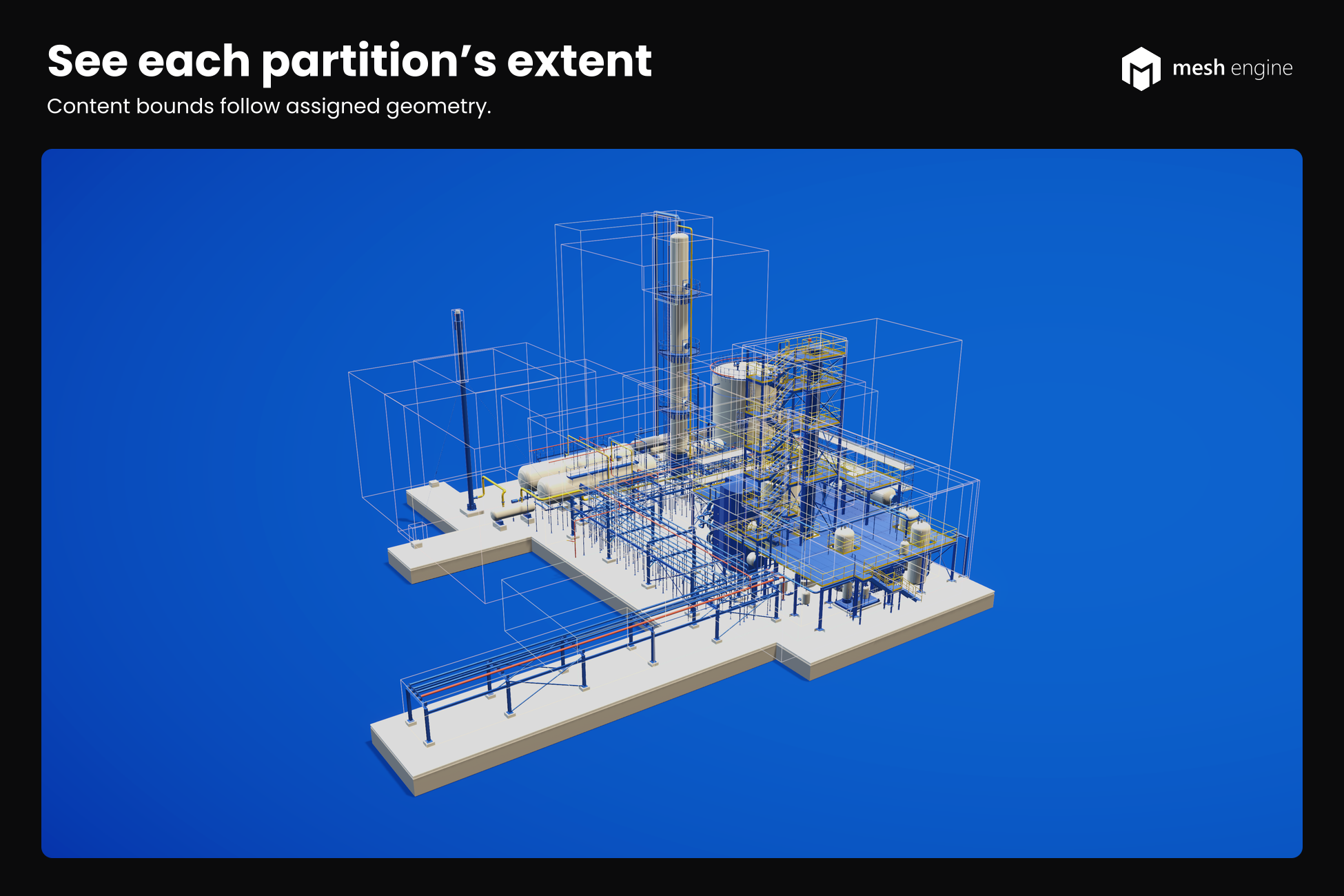
Where available, Partition bounds shows the actual extents of the generated geometry. These bounds can overlap or extend beyond their grid cells because Mesh Engine assigns whole triangles; it does not cut triangles at cell boundaries.
The comparison controls use the supplied output. Inspect new results separately in the Hierarchy and disable those copies before returning to the comparison.
The QuickStart profile restores shared settings for this example, including bounds, materials, reduction and output options. It retains the current source queue and overrides. After loading, keep only 150-P-103 queued and confirm its row shows Shared. You can configure a result manually instead; the User Guide explains those controls.
Fresh general defaults differ from the QuickStart setup: a 4 × 4 × 4 grid, original LOD0 plus three reduced targets of 65%, 45% and 25%. The default screen-height transitions are 75%, 50%, 25% and a 1% cull threshold. Existing working settings and loaded profiles retain their own values.
User Guide.
The Guided window has four views: Models, Configure, Output, and Inspect. The footer opens Configure with Review settings, then Output with Choose output. A wide window keeps the model sidebar visible; in a narrow dock, Change opens Models. The Quick Start walks through a first result; this guide covers the controls used for repeat work.
Source, grid and preview
In Models, assign a static source or use Add selection. Add model creates another source slot, and Remove removes a row from the queue. Select a row to review its effective settings and preview. Every queued model is included in the run. Missing or duplicate sources must be reassigned or removed before generation.
In Configure, Shared grid divisions sets the cell count along X, Y and Z. Each included triangle belongs to exactly one cell, according to its centroid. Triangles remain whole, so a cell's actual content can extend beyond its grid box and its output bounds can overlap neighbouring cells' bounds. One cell may produce several mesh segments because of material layouts, vertex attributes or size limits.
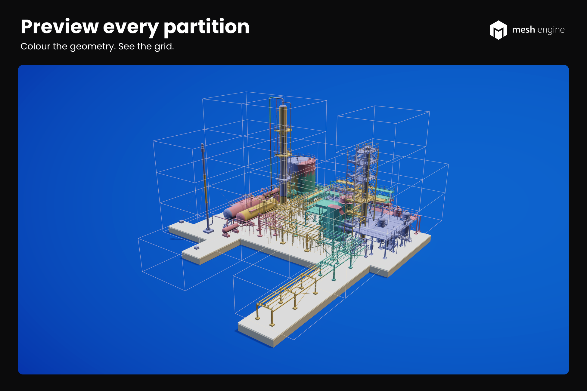
Under Partition preview, Preview partitions analyses the selected row without saving output assets. It colours the actual included geometry by spatial partition, with thin bounds for context. Colours repeat across the grid, and each partition keeps one colour across material and mesh-segment splits. Expand Partition preview > Preview appearance to inspect materials, focus, bounds, labels, occupied-cell visibility or slices. Show in Game view displays the same coloured geometry and bounds through the main camera; labels remain in Scene view. Clear preview releases the temporary preview and restores the source. Preview is optional; generation performs its own geometry checks. Dense preview supports at most 32,768 grid cells (X × Y × Z), including a 32 × 32 × 32 grid. Larger grids can still generate output from occupied regions; their dense preview is refused without changing the settings.
Set Bounds display to Content Bounds to fit each preview box to the geometry assigned to that partition. Empty cells are omitted and boxes can overlap because triangles remain whole. Grid Bounds shows the regular allocation cells instead. Slice axis and Slice index filter bounds to one layer; geometry remains complete. These display options do not change the generated geometry. Fresh preview settings show occupied cells with labels off; existing profiles retain their saved preferences.
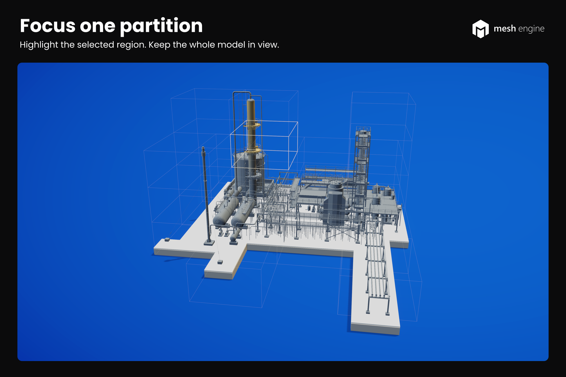
Choose Focus partition to emphasise one occupied spatial partition while surrounding geometry becomes muted. Original materials restores the source material references and disables colour focus. Colour previews use temporary lit materials, meshes and supported alpha masks; source and generated assets stay unchanged. Partition colouring simplifies authored surface effects, and custom shaders or renderer-specific shading can look different. Scene visibility is respected in Scene view. Demo comparison previews and the window preview release one another when activated.
Under Advanced settings > Bounds & exclusions (shared), automatic bounds enclose included source geometry. Selection bounds use Bounds root; custom bounds use Custom centre, Custom size and Padding. Bounds must enclose all included geometry in every mode. Generation rejects bounds that exclude included geometry. These controls define the grid; they do not select or crop source triangles. Fit bounds explicitly fits the grid to included geometry.
Inactive objects, disabled renderers and existing LOD1+ renderers are reported as exclusions. The optional Outlier filter removes renderer groups, not individual triangles; leave it off unless the omitted groups are intentional. Inspect its exclusions in the preview before generating, and expand Result details afterward to identify omitted objects and their reasons.
LOD targets and transitions
LOD0 keeps the included base geometry. Reduced LOD levels accepts one to three additional levels. Each LOD n slider and percentage field edits the same target percentage of the base triangle count, not a guaranteed result. Read the achieved retained and reduction percentages under Inspect.
Advanced settings > Screen-height transitions controls Unity's native LODGroup thresholds. These percentages describe how large the object appears on screen, independently of retained geometry. With the default three reduced levels, LOD0 switches below 75%, LOD1 below 50%, LOD2 below 25%, and LOD3 is culled below 1%. Active thresholds must descend, with culling below the last active switch. These are not distances in metres.
Reduction & quality contains Quality preset, Reduction strategy, and optional tuning. The fresh default uses Normal reduction with Topology safety enabled. Selecting Low, Medium or High sets Reduced LOD levels to three and replaces the targets and transitions. Selecting Custom preserves those values. Closing an advanced foldout preserves its values.
Boundary protection can prevent a requested reduction. A constrained result keeps more triangles; a rejected candidate may use a previously validated level or the original geometry. Result details explains the outcome. Optimise meshes and Generate secondary UVs are off by default, and their output must pass the same protection checks. See Compatibility and Limitations for the geometry contract.
Generate and find outputs
In Output, use Generate to create partitions and LODs. Other operations contains Generate partitions only and Generate LODs only.
Choose Output folder (shared) inside Assets. An empty field uses Assets/InfinitusInteractive/MeshEngine/Generated. A batch adds source-named subfolders beneath the shared destination. The displayed destination is the parent for a new Set-… folder; Show in Project opens the exact saved set after success.
A set contains generated meshes, materials, optional LODs and prefab, plus OutputSet.asset, which records the set's ownership and source information. Keep this complete set and its Unity metadata together. Output options controls scene hierarchy creation, prefab creation and source hiding. Hide source after success affects a scene source only after a successful run; it is off by default.
Inputs are locked during generation. Cancel requests a stop at a safe point and may wait for the current operation. Inspect each result's status. Failure or cancellation preserves prior valid output where restoration succeeds; if restoration requires attention, the result identifies the recovery journal. A failed row does not erase earlier successful batch results.
Keep or replace a set
Keep existing creates an independent set on every successful run. To replace a specific set, choose Replace selected output and assign its OutputSet.asset to Exact output to replace for that source row.
Replacement checks the selected set's recorded ownership, identities and saved content. Mesh Engine does not choose files to delete from the source name, source identity or folder naming convention. If the set is missing, changed or cannot be trusted, replacement is refused. Generate a new set from the source, or preserve a separate copy of edited meshes for the limited standalone workflow.
Scene Undo and file recovery are separate. Unity Undo covers generated scene objects and source visibility; it does not restore generated asset file contents. Replacement can retain older owned files needed by scene Undo or references in closed scenes. Those retained files are not a promise that Undo restores earlier mesh data.
If a run reports recovery is required, preserve the affected files and use Recover interrupted output… in the Mesh Engine window menu. Select the reported journal from the project's .mesh-engine-recovery directory. Recovery verifies recorded files and backups before restoring prior output, and refuses conflicting changes. It is not a general rollback command for arbitrary edits. Keep the journal and backups if it cannot complete, and contact Support.
Profiles and working state
In Configure, expand Advanced settings > Settings profile (optional) to assign a profile. Press Load to apply it; selecting it alone has no effect. Save updates the selected profile from the shared settings. Save As… creates a separate profile.
A profile stores shared grid, bounds, mesh/material, LOD, reduction, output, preview and batch preferences. It does not store source rows, per-source overrides, exact replacement choices or the scene bounds-root reference. Loading retains the queue and overrides, so review each row's Shared or Custom status after loading.
Profiles in an unsupported format cannot be loaded or overwritten. Save As… saves the current working settings as a separate profile.
The window remembers project-local working settings and source rows separately from profiles. This state is stored in the project's Library and is not a portable saved job or backup. Saved-scene references require that scene to be open; unsaved scene objects cannot be reliably recovered after restarting Unity. Reassign unresolved references when the window reports them. Reset shared settings… in the window menu restores shared defaults after confirmation; it does not delete generated assets.
Batch and source overrides
Add several sources and use the same generation action. Shared settings apply unless a row has enabled overrides. Batch: continue on error in Output options determines whether processing continues after a failed row; cancellation stops the batch.
Select the row, then expand Advanced settings > Selected source overrides. Turn off Use shared settings and enable only the needed group: mesh/materials, LOD targets/folders, or output policy/hierarchy. Disabled groups retain their custom values while using shared settings. Copy shared values into overrides and Clear selected overrides are explicit changes to that row.
Grid divisions, bounds, reduction safety and the main output folder remain shared. A profile does not populate the queue or clear existing overrides.
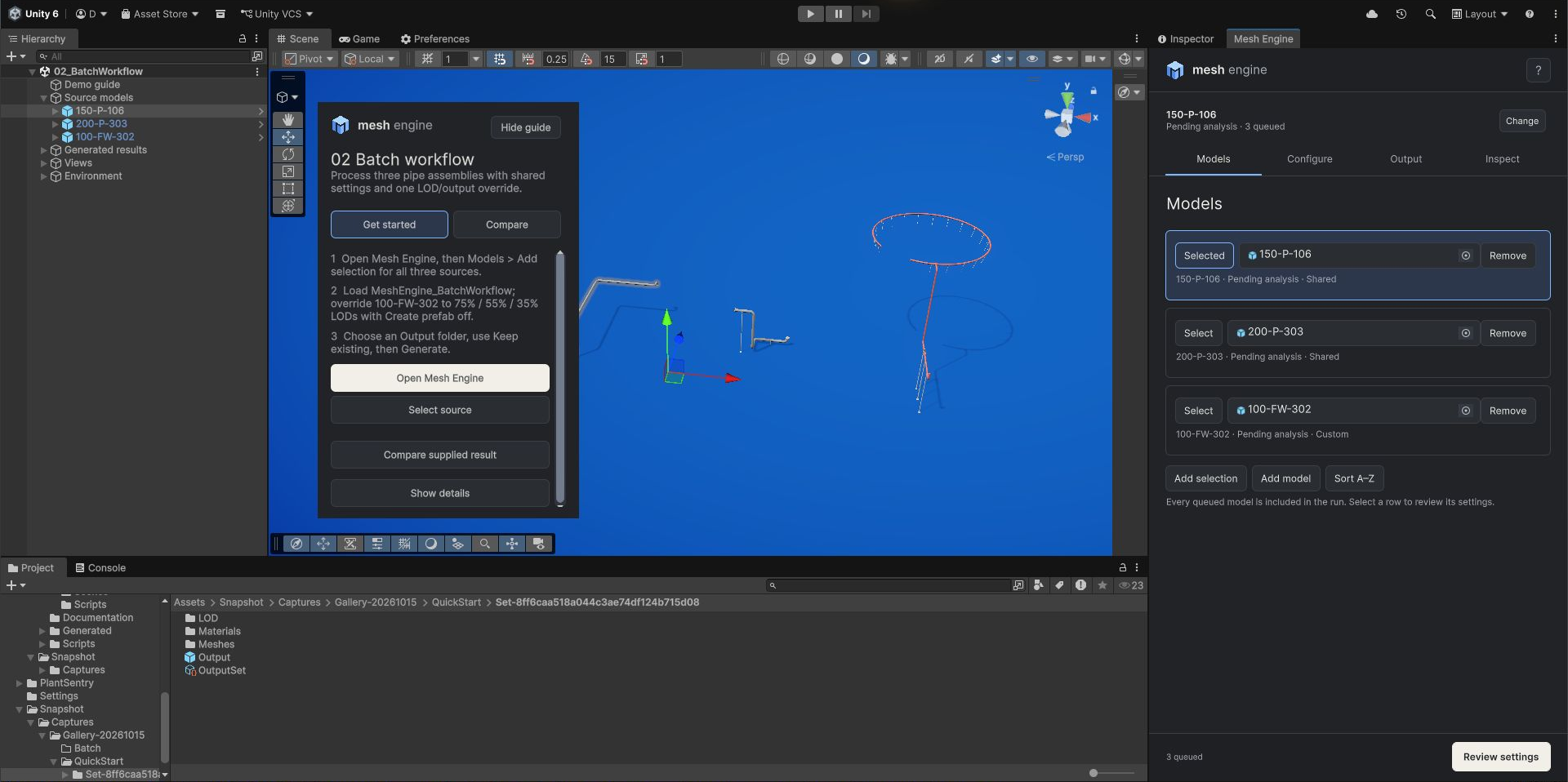
To reproduce 02_BatchWorkflow:
- Choose Select source in the scene guide, then Open Mesh Engine and Models > Add selection. Keep only
150-P-106,200-P-303and100-FW-302in the queue and retain their supplied transforms. To rebuild the scene sources, instantiateDemo/Prefabs/Plant_150-P-106_Source.prefab,Plant_200-P-303_Source.prefabandPlant_100-FW-302_Source.prefab, retaining each saved root transform. Add world translations of(-12, 0, 0),(0, 0, 0)and(12, 0, 0)respectively to those root positions, then add the scene instances to Models. - Load
Demo/Profiles/MeshEngine_BatchWorkflow.asset. Confirm each row shows Shared; enable Use shared settings for any row showing Custom. The shared setup uses a2 × 1 × 2grid, two reduced levels with65%/45%retained targets, Normal reduction and Topology safety. - Select
100-FW-302. In Advanced settings > Selected source overrides, choose Clear selected overrides, then Copy shared values into overrides. Turn off Use shared settings and enable only Override LOD targets & folders and Override output policy & hierarchy. - With
100-FW-302selected, set Reduced LOD levels to3and retained targets to75,55and35. In Output > Output options, turn Create prefab off and leave Create scene hierarchy on. - Choose an Output folder (shared) and confirm Keep existing for each source, preserving the supplied sets. Keep Create scene hierarchy and Create prefab on for the two Shared rows, and Hide source after success off for all three. Select Generate and inspect each result.
150-P-106and200-P-303produce prefabs and scene hierarchies;100-FW-302produces a scene hierarchy with its custom LOD targets and no prefab.
Full Plant comparison
- Open
03_PlantShowcase, choose Select source, then Open Mesh Engine and Models > Add selection. Keep only the prepared Complete plant source queued at its supplied transform. To rebuild the source, instantiateDemo/Prefabs/Plant_Complete_Source.prefab, retain its saved root transform and material assignments, then add that scene instance to Models. - Load
Demo/Profiles/MeshEngine_PlantShowcase.assetand confirm the source row shows Shared. Review a2 × 2 × 2grid, two reduced levels with65%/45%retained targets, Normal reduction and Topology safety. - Choose an output folder and use Keep existing to generate a separate result. Keep Create scene hierarchy and Create prefab on, with Hide source after success off. Use Show in Project, Select generated object and Result details to inspect the saved output and any constrained or fallback segments.
The prepared source joins the shell and both heads of each of V-106, V-107 and V-108 into one continuous vessel mesh. Each vessel uses an individual copy of its original material, retaining the original appearance and a shared reduction budget across its shell and heads. The saved source transform and material assignments are part of the reproduction recipe.
Compare the supplied Source and LODs from the same saved viewpoint, then use Automatic while navigating to inspect native transitions and neighbouring partitions. Regenerating the complete Plant takes substantially longer than QuickStart. See Compatibility and Limitations for its achieved counts and conservative outcomes.
Generate LODs from existing meshes
For an existing Mesh Engine set, assign its OutputSet.asset to Existing output for LODs in Output options, then use Generate LODs only. Its recorded base geometry and boundary information are validated before use. LOD output folder applies to this operation; combined generation keeps its output together.
Standalone mesh folder accepts separate main Mesh .asset files outside generated sets. Imported model subassets are not standalone inputs, and input/output folders must not overlap. This route has no cross-file boundary information or material assignments: use Material override if needed. Generate from the original source for the full source and boundary record.
Compatibility and Limitations.
Mesh Engine processes static meshes in the Unity Editor. Generation is an editor workflow; it does not simplify animated or skinned content at runtime. The supplied Plant scenes use URP materials.
Tested environment
Pre-release package import and editor workflow checks used Windows with Unity 6000.3.11f1 / URP 17.3.0 and 6000.4.4f1 / URP 17.4.0. The package compiled and imported with Input System absent; separate configurations used Input System 1.19.0. Mesh Engine does not require Input System. A Windows player build succeeded in Unity 6000.4.4f1; mesh generation remains editor-only.
The supplied demo results below were checked through native generation in Unity 6000.4.4f1 / URP 17.4.0.
On 12 October 2026, a pre-release candidate passed clean package import and compilation, followed by validation in a separate editor process, on Windows with Unity 6000.3.11f1 / URP 17.3.0 and 6000.4.4f1 / URP 17.4.0. Both projects used fresh official URP template settings without Input System. Native integrity checks loaded all three demo scenes and five supplied output sets and found valid shaders on all 122 distinct scene materials. These import and integrity checks did not repeat LOD generation, a player build or rendered visual QA.
During that pre-release validation, Unity 6.4 reported two GUID compilation errors in its Shader Graph package. Unity's automatic API updater repaired those package-cache references, after which compilation and validation succeeded. The initial Unity 6.4 import log was not error-free.
These checks do not qualify other Unity versions, operating systems, Built-in Render Pipeline or HDRP. Material compatibility depends on the shaders available in your project.
Input requirements
Choose a scene object, prefab, FBX model asset or direct Mesh input. A direct Mesh is processed as one source mesh instance; it does not require a scene renderer. Included meshes must be readable, contain indexed triangle geometry and have finite vertex data. Enable Read/Write in an imported model's settings when needed.
Hierarchy input uses MeshFilter/MeshRenderer pairs on active objects with enabled renderers. The GameObject Static checkbox is not required. Existing LODGroups contribute LOD0 content. Inactive objects, disabled renderers and lower existing LODs are reported as exclusions. Renderer types other than MeshRenderer and SkinnedMeshRenderer are also reported as exclusions.
An included SkinnedMeshRenderer stops the run with an unsupported-skinning error. Unsupported included mesh content also stops the run: this includes skinning, blendshapes, unreadable or empty meshes, unsupported vertex layouts, invalid indices, non-triangle topology and nonfinite data. An included MeshRenderer without a MeshFilter or assigned mesh is an error.
Nonuniform and mirrored transforms are handled when finite and invertible. Zero-scale or otherwise singular transforms are rejected. Generation bakes source placement into its output frame; it does not preserve an animated transform hierarchy.
Attributes, materials and bounds
Partitioning preserves material slots and valid source normals, tangents, colours and UV channels 0–7, including their original dimensions. It does not join vertices merely because their positions match. Mirrored transforms receive the corresponding winding and tangent-handedness treatment.
A direct Mesh asset carries no renderer material assignments. Missing material slots remain empty unless you provide Material override. Source materials are copied for generated output. Material override selects the material to copy; enabled Apply colour filter applies to that copy, including an override. Disable filtering to retain its copied colour. These controls do not repair missing shaders or translate a material to another render pipeline.
Whole triangles are assigned once by centroid. There is no clipping, capping or implicit cropping at grid boundaries. Actual output bounds enclose the assigned triangles and may extend outside their grid cells. Bounds must enclose all included geometry in every mode; change the source selection or an explicit exclusion to change the content.
Dense preview and the overlay component's automatic or manual bounds rebuild support at most 32,768 grid cells (X × Y × Z). Larger dense visualizations are refused; a refused overlay rebuild retains existing cached bounds. This limit does not restrict sparse generation, supplied partition bounds, saved outputs or valid grid/profile values.
Cells may contain multiple segments for different material/attribute layouts or vertex limits. Larger cells can be split into valid indexed segments, including for 16-bit indices. Segment counts therefore need not match occupied-cell counts.
Boundary protection and conservative results
The protected editor LOD path preserves existing shared boundary positions and edge chains, including boundaries introduced by segmentation. Candidates are checked against source boundary information and neighbouring segments at different LOD levels. This protection does not repair pre-existing gaps, merge disconnected surfaces or infer adjacency from matching positions.
Requested retained percentages remain targets. Boundary or topology constraints can leave a larger result, including an unchanged mesh. A candidate that fails validation can reuse a suitable earlier validated level or retain original geometry; the result reports actual counts and the reason.
Finite zero-area triangles are retained conservatively when part of an otherwise usable source. A source containing no nonzero-area surface is rejected. One-component UV channels and some ambiguous topology can also require original retention. Optional optimisation or secondary-UV generation is not applied when it cannot preserve the required layout, boundary attributes or source correspondence.
Standalone LOD inputs have only their own mesh information. They do not inherit renderer materials or a guarantee of continuity between separate files. Owned output sets retain the source and boundary information recorded during generation; keep their manifests and owned assets together and avoid editing them in place if you need to reuse or replace the set.
Output sets and version control
Output sets that record support for line-ending tolerance accept ordinary Git LF/CRLF conversions in eligible Unity text files for generated meshes, materials and prefabs. Each file must use uniform LF or CRLF endings, with no other content changes. Actual content or identity changes still prevent the set from being reused or replaced as trusted output.
Keep complete output sets together with their .meta identities. Binary files must remain byte-for-byte intact. This tolerance does not cover mixed line endings, encoding changes, reformatting, custom Git filters or forcing binary files through text conversion.
Sets without recorded line-ending tolerance require exact file matching. File recovery always checks exact bytes.
Supplied results
These are the saved triangle counts from the supplied source recipes and placements, using imported Unity geometry. They are not promises for other models:
| Example | Grid | Requested retained targets | LOD0 | LOD1 | LOD2 | LOD3 |
|---|---|---|---|---|---|---|
| QuickStart 150-P-103 | 2 × 1 × 2 | 65%, 45% | 4,640 | 3,234 | 2,434 | — |
| Batch 150-P-106 | 2 × 1 × 2 | 65%, 45% | 3,644 | 2,588 | 1,984 | — |
| Batch 200-P-303 | 2 × 1 × 2 | 65%, 45% | 3,168 | 2,306 | 1,822 | — |
| Batch 100-FW-302 | 2 × 1 × 2 | 75%, 55%, 35% | 20,704 | 16,148 | 12,504 | 10,884 |
| PlantShowcase — Complete plant | 2 × 2 × 2 | 65%, 45% | 656,956 | 558,466 | 517,520 | — |
| Example | Included source mesh renderers | Occupied cells | Segments | Constrained segments, LOD1 / LOD2 / LOD3 |
|---|---|---|---|---|
| QuickStart 150-P-103 | 47 | 3 | 8 | 2 / 2 / — |
| Batch 150-P-106 | 38 | 3 | 8 | 4 / 3 / — |
| Batch 200-P-303 | 35 | 3 | 11 | 6 / 6 / — |
| Batch 100-FW-302 | 223 | 4 | 22 | 17 / 16 / 22 |
| PlantShowcase — Complete plant | 13,302 | 7 | 131 | 100 / 116 / — |
QuickStart reduces its triangle count by approximately 30.3% at LOD1 and 47.5% at LOD2. The small examples contain constrained segments but use no original fallback geometry. The Batch example demonstrates two Shared rows and custom LOD targets plus scene-only output for 100-FW-302.
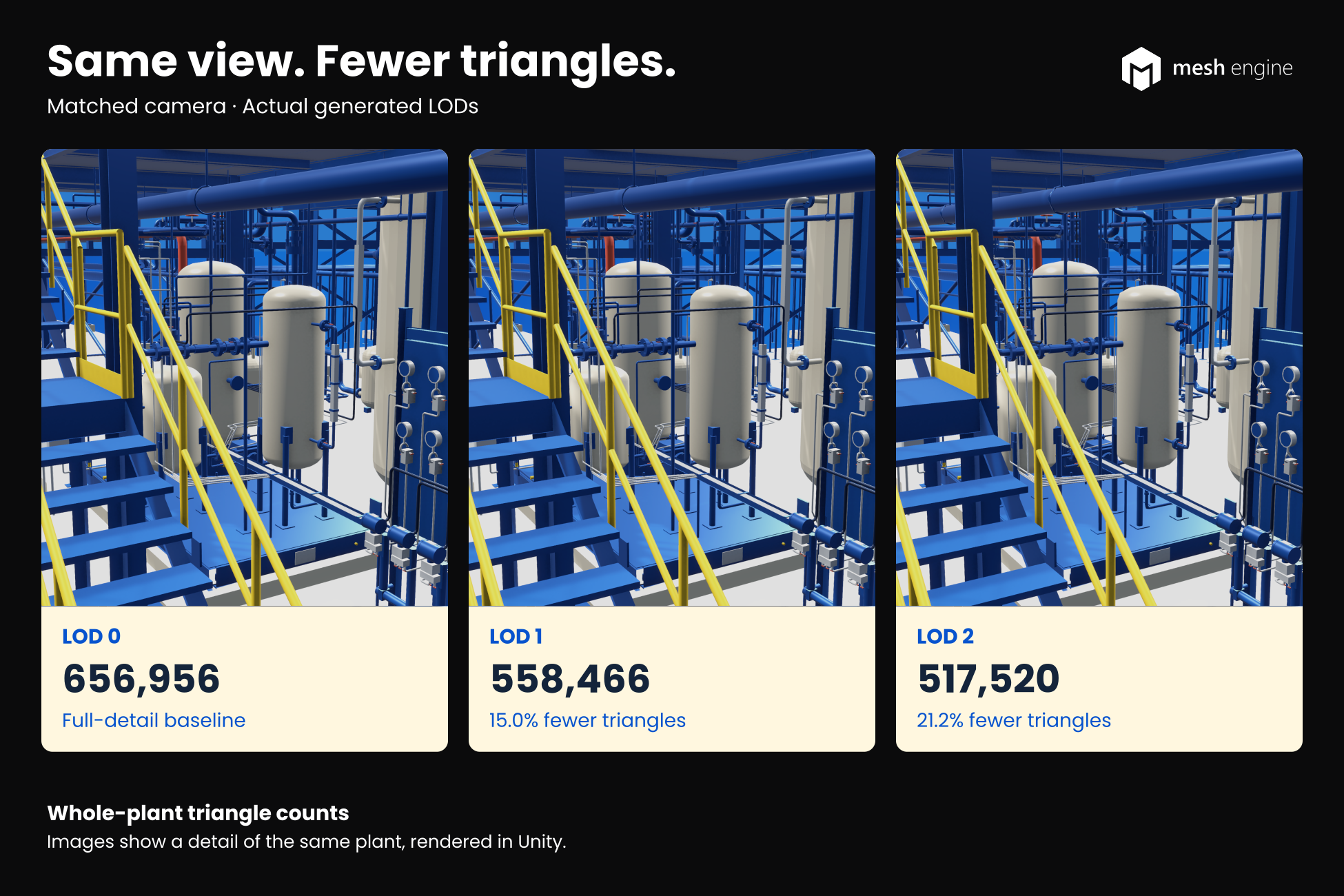
The complete Plant retains approximately 85.01% and 78.78% of its LOD0 triangles, giving 14.99% and 21.22% reductions. The imported source contains no finite zero-area triangles, and the supplied result uses no original fallback geometry. At LOD2, 87 of 131 segments retain their original triangle count. None of the supplied examples reuses an earlier reduced level.
The full Plant scene uses an instance of Plant.fbx with an individual material copy assigned to each of its three vessels. Plant_Complete_Source.prefab provides the matching reusable prepared source. Each vessel shell is joined to its two heads as one continuous mesh. The material assignments keep the three vessels in separate reduction groups with their original appearances. Native LOD selection and culling determine which groups are visible. Retain the prepared source transform and material assignments to reproduce these counts.
The triangle totals sum every segment at the named LOD. Automatic mode selects levels independently and can cull segments, so the visible total changes with the view. Each segment stores a renderer for each LOD; counting every renderer component in the hierarchy adds all stored levels rather than the geometry currently drawn. Occupied-cell and segment counts are also distinct.
The supplied profiles use Normal reduction and topology safety, with mesh optimisation, secondary-UV generation and material colour filtering off. Use the saved comparisons to inspect achieved geometry and appearance together. Regenerating the complete Plant takes substantially longer than QuickStart. Different source placement, content, settings or import results can produce different outcomes; compare achieved counts and appearance for your own project.
Troubleshooting.
Start with the message beside the generation action. Details explains configuration and inclusion problems; Result details explains a completed, failed or cancelled run.
Generation is unavailable or fails
Assign a supported source, remove duplicate or missing rows, and use positive Shared grid divisions. Check that imported meshes have Read/Write enabled. An included skinned mesh, invalid geometry or an enabled renderer without a mesh must be corrected or removed from the selected source.
If Replace selected output is active, assign the exact set to Exact output to replace, or choose Keep existing. For Generate LODs only, assign an existing output set or a valid standalone mesh folder.
If a source or dependency changes during generation, let the import/edit finish and start a new run. The previous result is not evidence that the changed source has been processed.
Preview or bounds do not match expectations
Select the intended source row and press Preview partitions again. Dense preview and overlay bounds rebuilding support at most 32,768 grid cells (X × Y × Z). For a larger grid, generation remains available and processes occupied regions. A refused overlay rebuild keeps its previous cached bounds. Review Preview appearance, including occupied-cell and slice controls; these change the displayed preview, not the generated content.
Bounds must enclose included geometry in every mode. If generation reports excluded geometry, use Fit bounds or correct the source selection. Custom and selection bounds never crop triangles. To omit a component, select a narrower source hierarchy or make its exclusion explicit. If Outlier filter is enabled, inspect the reported groups and turn it off if it removes content you need.
A triangle can extend beyond the cell containing its centroid. Use the content-bounds display to inspect the space occupied by whole assigned triangles. If output is too fragmented, try fewer Shared grid divisions; differing materials and layouts can still produce multiple segments per cell.
LODs retain more geometry than requested
Read the achieved percentages and Result details. Boundary and topology constraints can prevent further reduction. An original fallback is a reported conservative result, not an achieved target. Lowering the target or choosing a more aggressive strategy may not reduce protected geometry.
For a result that loses too much detail, raise its retained percentage and inspect the silhouette again. Keep Topology safety enabled as a starting point.
LOD switching or culling looks wrong
Check Advanced settings > Screen-height transitions. These are percentages of screen height, not metre distances. The active switch values must descend, and Cull below (%) must be below the final switch. Changing retained percentages changes mesh detail; it does not set the switching distance.
In the demo scenes, choose Automatic to return from a forced manual level to native LOD selection. The buttons refer to supplied outputs only. Disable newly generated copies before using that comparison again.
Materials are missing or look different
Inspect source material slots and confirm their shaders are available in the active render pipeline. Direct Mesh inputs and standalone meshes do not carry renderer material assignments. Assign Material override when you need an explicit material. Material override selects the material copied for output. Enabled Apply colour filter applies to that copy, including an override. Turn filtering off to retain its copied colour.
Existing output cannot be reused or replaced
Keep OutputSet.asset, its owned assets and their Unity metadata together. A similar folder or source name is insufficient. Dirty, edited, missing or untrusted output is refused to avoid replacing content whose ownership cannot be established.
Preserve the existing set and generate a new one from the source. For intentionally edited mesh copies, use a separate standalone folder only if its reduced source information is acceptable. Do not edit the ownership record to bypass the check.
If a failed or cancelled run reports a recovery journal, preserve the affected files and open Recover interrupted output… from the Mesh Engine window menu. Select that journal. If recovery reports a conflict, keep its files and contact Support. Scene Undo does not restore asset file contents.
A profile or source row did not restore
Assigning a profile does not apply it: press Load. Loading replaces shared settings but retains source overrides, so check whether the selected row is Custom. Use Save As… to preserve working settings separately from the selected profile.
For an unresolved scene source, open its saved scene or reassign the row. Local working state is not a saved job and cannot restore an unsaved object after an editor restart. If the window reports corrupt or unsupported state, preserve it and include that message in a support request.
A batch stopped early
Inspect the result for each source. Batch: continue on error controls whether the next row runs after a failure. Cancellation stops processing, and remaining rows can be marked NotStarted. Successful earlier rows keep their own outputs.
Support.
Contact support@teaminfinitus.com for questions about Mesh Engine or help with the workflow.
Describe the action you ran, what you expected and what happened. Include:
- Mesh Engine version, Unity version, operating system and active render pipeline.
- Source type, the selected generation action and whether the row uses shared settings or overrides.
- The output policy and folder, plus the exact message from Details, Result details or the Console.
- Short reproduction steps and a screenshot of the relevant settings and result.
A small source that reproduces the issue helps, if you can share it. Say whether the same issue occurs with a supplied demo component. For an interrupted write or recovery failure, preserve the affected output, journal and backups, and include the reported recovery path. Do not modify them to suppress an ownership error.
You can contact support directly; Troubleshooting is available for a quick check. For attribution questions, see Third Party Notices.
First Release.
First release overview
Mesh Engine is being prepared for its first public release. This guide describes the included workflow, Plant examples, partition preview and output handling.
Guided workflow and Plant examples
The editor presents one dockable workflow: select a model, review settings and optional preview, generate, then inspect the result. Generate creates partitions and LODs in the Guided window. Profiles, source overrides and secondary operations are expandable.
Fresh settings use a 4 × 4 × 4 grid, original LOD0 and retained targets of 65%, 45% and 25%. LOD transitions use native screen-height percentages. Existing working settings and loaded profiles keep their preferences, and assigning a profile requires an explicit Load.
Partitioning assigns whole triangles once, preserves source attributes and material slots, and reports exclusions. The protected LOD path validates boundaries and can retain larger or original geometry when a target cannot be met. Results distinguish requested targets, achieved counts and fallback reasons.
Output sets record ownership and source information. Keep existing creates independent results; Replace selected output requires an explicitly selected, trusted set. Results link to saved assets and scene objects. Interrupted writes report recovery information separately from scene Undo.
The numbered examples use the Plant model: a 150-P-103 pipe assembly QuickStart, a three-component batch and a full-plant comparison. Guidance and comparison controls are available directly in Scene view and use the supplied outputs. QuickStart combines 47 source mesh renderers into 8 segments across three occupied cells; its two reduced LODs contain 3,234 and 2,434 triangles from a 4,640-triangle source. LOD2 reduces the triangle count by approximately 47.5%. The batch example processes 150-P-106, 200-P-303 and 100-FW-302, with custom LOD targets and scene-only output for 100-FW-302.
The complete Plant uses a prepared whole-model source with three continuous vessel meshes formed by joining their shells and heads. Each vessel has its own material copy retaining its original appearance. It uses a 2 × 2 × 2 grid and two reduced levels. Its 131 segments contain 558,466 and 517,520 triangles from a 656,956-triangle source; LOD2 reduces the triangle count by approximately 21.22%. The material grouping keeps the three vessel assemblies separate during reduction. The imported source contains no finite zero-area triangles, and the supplied result uses no original fallback geometry. The Compatibility and Limitations guide lists the saved counts, constrained segments and generation considerations.
Project requirements
Mesh Engine does not require Unity's Input System package or a change to the project's input backend. The supplied demos use fixed viewpoint controls and URP materials. See Installation and Setup and Compatibility and Limitations for the tested environment and source requirements.
Third Party Notices.
Mesh Engine includes UnityMeshSimplifier source code for mesh reduction. Its original source licence headers and attribution notices remain part of the distribution under Assets/InfinitusInteractive/MeshEngine/Scripts/Runtime/UnityMeshSimplifier.
The Plant model is copyright (c) Infinitus Interactive. The model and its included component prefabs and generated examples are supplied under the Unity Asset Store standard End User License Agreement; see Demo/Models/License.txt. Unity package dependencies, including the URP shaders used by the demos, retain their own package notices.
UnityMeshSimplifier
The following notice is reproduced from the included source:
MIT License

Copyright(c) 2017-2020 Mattias Edlund

Permission is hereby granted, free of charge, to any person obtaining a copy
of this software and associated documentation files (the "Software"), to deal
in the Software without restriction, including without limitation the rights
to use, copy, modify, merge, publish, distribute, sublicense, and/or sell
copies of the Software, and to permit persons to whom the Software is
furnished to do so, subject to the following conditions:

The above copyright notice and this permission notice shall be included in all
copies or substantial portions of the Software.

THE SOFTWARE IS PROVIDED "AS IS", WITHOUT WARRANTY OF ANY KIND, EXPRESS OR
IMPLIED, INCLUDING BUT NOT LIMITED TO THE WARRANTIES OF MERCHANTABILITY,
FITNESS FOR A PARTICULAR PURPOSE AND NONINFRINGEMENT. IN NO EVENT SHALL THE
AUTHORS OR COPYRIGHT HOLDERS BE LIABLE FOR ANY CLAIM, DAMAGES OR OTHER
LIABILITY, WHETHER IN AN ACTION OF CONTRACT, TORT OR OTHERWISE, ARISING FROM,
OUT OF OR IN CONNECTION WITH THE SOFTWARE OR THE USE OR OTHER DEALINGS IN THE
SOFTWARE.
The included source also retains this original attribution:
/////////////////////////////////////////////
//
// Mesh Simplification Tutorial
//
// (C) by Sven Forstmann in 2014
//
// License : MIT
// http://opensource.org/licenses/MIT
//
//https://github.com/sp4cerat/Fast-Quadric-Mesh-Simplification
Local simplifier changes
Mesh Engine adds explicit protected vertices and prevents their linking or collapse. Protection and original vertex identities survive attribute expansion and compaction; attribute indices are remapped for later calls. Local corrections address flat-X linking, integer overflow in hash comparisons and protected tangent handedness. Declared UV dimensions, including present zero-valued channels, are retained.
The static editor path disables position linking and protects source boundary edges. It checks edge coverage, endpoint attributes, material slots, UV layouts and topology after reduction and optional processing. Pre-existing disconnected vertex fans retain their exact incident triangles while other valid geometry can reduce. Invalid candidates use a validated earlier level or original geometry, with actual counts and reasons reported.
The protected editor path uses requested retained percentages directly. Reduction tuning controls convergence; it does not override those targets or requested safety. Using the editor workflow does not rewrite saved profile assets.
These changes preserve existing boundaries. They do not repair source gaps or infer continuity between standalone mesh files. Keep the original licence and attribution headers with the included source when redistributing it.
Interested in where Mesh Engine is heading?
Read through the documentation, then get in touch if you want to discuss the roadmap, the workflow fit, or a custom implementation around similar systems.